Acquiring good CCD images requires planning. The optical and CCD system should be configured for the type of object to be imaged.
a. Deep-sky vs solar/lunar/planetary imaging. Shooting bright objects such as the Moon or the planets requires a "slower" optical system and very short ("snapshot") exposure times to keep the CCD pixels from saturating. Even the fastest exposure time available, usually 0.01 second or so, cannot keep the Moon from saturating a CCD if the optical system's focal ratio is less than about f10. Also, the longer effective focal lengths yielded by Barlow lens or eyepiece projection not only reduce pixel saturation, but provide better sampling of the high-resolution PSFs that are produced with snapshot imaging.
On the other hand, deep-sky imaging should be accomplished with the fastest optical system (i.e., smallest focal ratio) that can be used without inducing vignetting, field curvature, or other optical limitations. F6 or faster optical systems with focal lengths that allow the pixels to sample the PSFs in accordance with the Nyquist criterion of at least 2 samples per PSF (see "Sampling" in the Glossary of Terms) are optimal for deep-sky work. Of course, faint deep-sky objects also require long exposure times rather than snapshots. This means that telescope drive performance is critical. If well-tracked unguided imaging is the goal, then drive polar alignment and performance must be adequate to allow exposures of at least 15-20 seconds without PSFs (stars, etc.) wandering more than about 25-30% of the diameter of a pixel. This is an extraordinary requirement for most commercial drives! Fortunately, if these requirements are met, short unguided CCD exposures can be calibrated and stacked (summed or averaged) to achieve nearly the same high signal-to-noise (S/N) ratio of long single exposures of equivalent total duration. Guided imaging, either manual or autoguided, will allow longer subexposures to be made and stacked. Guided or unguided, it is wise to stack subexposures rather than trying to capture a full 20 minutes, one hour, or longer total exposure in one integration. Long single exposures run increased risks of pixel saturation, tracking problems, and image artifacts such as cosmic ray hits, satellite trails, etc.
b. Focus criticality and methods. Most camera control software programs have a "focus mode" that allows short, automatically repeating exposures to be made while the imager adjusts the focus on a star in the field of view. Usually this mode can be made to zoom in to a subset of the full CCD pixel array so that images of the chosen star can be displayed rapidly and at enhanced magnification. It is critical to take the time to assure that best focus has been achieved and to periodically check the focus throughout the night. Large Newtonian telescopes, particularly, can experience a change in focus due to large-scale scope movement and changes in ambient temperature.
There are a number of focusing methods that can be used to achieve best focus more rapidly than simple iterative viewing of star images. These include peak value, blooming spike maximization, and diffraction mask focusing. Although iteratively adjusting the focus of small, relatively faint stars will work nicely and will get you there, sometimes it is difficult to know when to quit! I highly recommend Bill McLaughlin's excellent detailed discussion of focusing methods which can be seen at http://nightskypictures.com/focus1.htm . There is very little I could add to Bill's thorough coverage.
c. Tracking tests. After reaching good focus and with the scope well aligned and tracking, you should take a series of fairly short integrations (e.g. 5-10 seconds, 15-20 seconds, and 30-60 seconds) to determine how long your scope's drive will allow you to go unguided before noticeable tracking errors occur. If you do not have a manual or automatic guiding system, you will usually want to make exposures at this maximum unguided time. These become subexposures that can be calibrated and stacked later during image processing to create a high-SNR, long-exposure result.
If you use manual or automatic guiding, you should be able to make well-tracked integrations many minutes long. Test images taken while guiding will allow you evaluate the quality of the tracking (i.e., effect of any flexure, guiding misalignments, etc.). In addition, test images taken at various integration times will allow you determine the limits of pixel saturation and sky background for your planned object frames. Even if you have perfect guided tracking and ABG protection, I would recommend against making any images longer than 5-10 minutes, since subsequent stacking of subexposures will allow compilation of indefinitely long integration times with concomitant high SNR and without the danger of losing too much valuable imaging time due to unavoidable artifacts in any given image. When passing headlights, friends with stray redlights, bright satellite trails, or other phenomena destroy a 5-minute image it is no disaster; but when a 30-minute effort is lost, it can be frustrating and linguistically challenging.
d. FOV and centering. Unless a pieced-together mosaic is planned, the objects to be imaged should be those that fit entirely within the FOV of the chip. This FOV can be determined as discussed previously in Section 1.a. and the Glossary. Most camera control programs have a "Find" mode (sometimes called "Find/Focus") which allows short, high sensitivity (i.e., binned) images to be downloaded quickly so that a new integration is shown every few seconds. With this mode, the imager can initially locate the object on the chip, then center the object or otherwise place it in the FOV for the desired image framing.
Systems with off-axis guiding may not always provide a usable guide star in the location which places the object in the desired framing. In these cases, unguided short exposures or mosaics may be better options.
e. Evaluating exposures. Immediately inspecting and evaluating integrations will help the imager make the right real-time changes to assure that the exposures can be processed later into good final images.
As mentioned in step 7 of JUST THE BASICS, integrating and storing a matching dark frame in the acquisition program's buffer will allow subtraction of the dark frame from the just-captured light frame so that SNR is improved. Since SNR is the defining parameter of picture quality (or "depth"), the improved SNR will allow the object(s) of interest to be seen as well as the acquired data will allow.
After dark subtraction, linear image stretching should be done to bring up the relative brightness levels of the objects in the image. Most programs have an "Autostretch" function which can accomplish this at the click of a mouse button or the activation of a keystroke. A linear stretch, which is a standard function of acquisition programs, sets a "low" pixel value, below which all pixels are shown as black (as if ADU = 0), and a "high" pixel value, above which all pixels are shown as white (as if ADU = 65535, assuming a 16-bit dynamic range). The pixel values in between are linearly stretched across the full dynamic range ( 0 to 65535) so that grayscale brightness levels can readily be seen and distinguished. Often, an image histogram, a logarithmic graph of the numbers of pixels at each brightness level in the image, is used with accompanying slider bars to set the low and high values at specific ADU levels or at specific percentiles of the unstretched image brightness range. I have found that a low percentile of 0.01 and a high percentile of 0.995 usually work quite well to display the important image details for quick-look evaluation purposes.
To see what is going on at the level of single pixels, most programs produce a readout of pixel values as the cursor is moved across the displayed CCD array. This is highly useful in determining the brightness level of the sky background, evaluating gradients across the array, and identifying areas where pixels have reached saturation. Areas where pixels that have been saturated cannot be processed so that image detail (i.e., brightness distinctions) can be seen. Once an area is all white, it stays all white, so one of the key image acquisition evaluation tasks is to assure that the integration time is not so long that areas of interest are saturated. For most deep-sky objects, this is not a concern, but the Trapezium region of the Orion Nebula, for example, can become saturated very rapidly!
If the camera has no anti-blooming gate (ABG), then bright stars that saturate quickly will cause voltage spillover from their central pixels to adjacent pixels, causing a rather ugly streak (called blooming). Although there are editing functions in many image processing programs which will help eliminate blooming streaks, unless long integration time is necessary to achieve sufficient SNR in an individual exposure, it is best to minimize the integration times for individual exposures and achieve higher SNR through image stacking (summing or averaging images). Cameras with ABGs can employ much longer integration times for individual exposures without saturating pixels adjacent to right stars, but at the expense of reduction in full-well capacity and sensitivity.
f. Achieving Good SNR -- The size of the uncertainty or noise associated with a CCD signal can be assumed to be the square root of signal. Thus, if the measured signal in a pixel is 100 ADU, the noise or uncertainty of the signal is 10 ADU, and the SNR is 10 (100 divided by 10). Increase the signal by a factor to 4 to 400 (by integrating 4 times longer) and the noise increases to 20 (square root of 400) and the SNR becomes 20. In short, SNR increases as the square root of the increase in signal, so imaging 4 times longer doubles the SNR. It is sometimes amazing to see how much better an image is with doubled SNR. Increase the exposure time by 36 and the SNR increases by a factor of 6, an amazing difference, which often reveals very faint deep-sky structures.
The name of the game for good images is improving the SNR and the way to do that for deep-sky objects is to image much longer, usually by shooting numerous subintegrations (integrations destined to be stacked), each of which may be a few minutes long. See http://www.kellysky.net/Newberry_SN.doc for the first part of the finest article ever published for the amateur on the issue of CCD imaging and SNR. This was written by Mike Newberry (author of MIRA software) and appeared as a two-part article in 1994 issues of the now-defunct CCD Astronomy magazine, published by Sky Publishing. Sky Publishing has their link offline for rework. In the interim, the cited link will allow you to read the first part of this fine article. Wherever you can find it available, I highly recommend the second part of the article also.
The complications of CCD imaging include the fact that numerous sources of signal and noise other than the object of interest are compiled in any CCD image. Other sources of signal and/or noise include foreground sky illumination, camera thermal environment, camera bias voltage, and camera readout electronics. Improving the SNR of any of the sources that produce both signal and noise will improve the final image of the object of interest, since the image will have been calibrated by subtracting better (i.e., more certain or higher-SNR) dark frames and dividing by better flat-field frames. Just as with the signal of the object of interest, the SNR of these other sources of signal and noise can be improved by increasing the amount of sampled signal, usually by making numerous integrations of these sources and averaging them. Camera readout noise is unique in that it has no associated signal and appears as a separate noise component in every camera integration.
g. Dark Frames -- The SNR of foreground sky illumination improves along with the SNR of the object of interest as more light frames are stacked, but the SNR of the camera thermal environment and bias voltage must be improved by stacking numerous dark frames whose integration times match the light frames. Dark frames are integrations that are made with the chip in total darkness. Not even the faintest light can be allowed to impinge on the CCD, so a light-tight methodology must be applied when taking dark frames. If the optical system is enclosed all the way to the chip (no light leaks in focusers, filter assemblies, etc.), then capping the entrance pupil of the telescope should be sufficient. If you use a filter wheel, it is handy to have a light-blocking position on the wheel for making dark frames.
Subtracting a high-SNR dark frame, usually a so-called "master" dark frame made by stacking numerous dark integrations, will greatly improve the SNR of a light frame, allowing the object of interest to be seen with much greater smoothness and certainty. This is called dark calibration. Stacking numerous dark-calibrated light frames of the same object will continue to improve the SNR, basically in proportion to the square root of the number of calibrated light frames that have been stacked. This improvement relationship falters slightly due to the fact that additional samples of readout noise are introduced with each camera integration; however, as long as the noise associated with signal sources such as sky illumination is much larger than the readout noise in each light frame, then SNR improvement by stacking compares well to SNR improvement by taking longer single light frames.
h. Flat-field frames -- Irregularities in the optical system and among the CCD pixels themselves can also introduce uncertainty into a light frame by changing the homogeneity of the response to light across the CCD array. Common sources of such irregularities include vignetting (obscuration of the light path by mechanical apertures), specks of dust or smudges on the optical elements closest to the chip, and slight differences in inherent pixel-to-pixel sensitivity across the chip. Fortunately, such irregularities can be smoothed or "flattened" by dividing the pixel values in a light frame by the normalized pixel values in a "flat-field frame". A flat-field frame is a picture of these irregularities made by pointing the CCD camera through the optical system at a smoothly homogeneous field of light and integrating until the pixels are filled by 20-50%. Pointing the telescope to a bright twilight sky, a large evenly illuminated screen, or to the inside of a specially constructed light box will allow such flat-field frames to be acquired with only a few seconds of integration time. As with normal light frames, high-SNR master flats should be made by stacking numerous dark-calibrated flat frames.
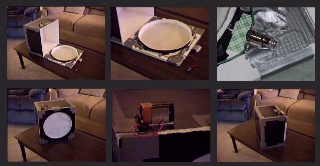
Enclosed tube assemblies, such as a refractor or an SCT, are perfect candidates for my rather simple but effective light box (see pictures below). It is made from foamcore board (any art supply place has it), black on one side, white on the other; duct tape to hold the box together; clear plexiglas and 5 mil vellum (or opaque white "milkglass") to make the diffuser screen that sits over the corrector plate/front end of the scope; 2.25-2.5 V white incandescent screw-type flashlight bulbs from Radio Shack; a battery or battery pack; and lengths of small-gauge conducting wire to hook the screw-in bases for the bulbs in series to the battery or battery pack. I use 4 bulbs and a 9-volt battery for my C-8 light box. They burn brightly and are easily replaced, but I have yet to burn one out.
Size the box for your scope. My C-8 box is 12"x12"x8"; for a 14-inch scope maybe 16"x16"x12" would be about right. (NOTE: Allen Gilchrist of Houston ran an analysis a few years ago which concluded that recessed-lit light boxes built this way should have a ratio of depth to width of about 70%.) The white side of the foamcore goes inside the box to let the recessed flashlight bulb light bounce around effectively before illuminating the diffuser screen. Recess the four bulbs in the lower corners of the box, behind low foamcore walls so that they cannot directly illuminate the diffuser screen but can shine upward to the white upper inside of the box and illuminate it very evenly. Make the diffuser screen by lining the inside of a square of clear plexiglas (same dimension as the planned bottom of the box) with two layers of 5 mil vellum. Even better, opaque white milkglass can be used, if you can find it. Make the bottom of the box by layering the diffuser screen between two similar squares of foamcore which have had a circular aperture cut out of their centers sized to fit over the end of the scope. The outer thickness of foamcore will act as a retaining ledge to hold the light box onto your scope even when it is not pointed right at the zenith.
The box is lightweight, self-contained, and star-party proof (it can be used in the middle of one without disturbing folks if you have taped over all potential corner light leaks).
i. Color Imaging-- Unless images are made with a single-shot color camera, such as the Starlight Xpress (SX) MX7C, color images must be made by separately integrating through filters with different passbands, such as RGB (red, green, blue) filters, then calibrating, processing, and compositing the images. Although I use an SX camera myself (an MX916) and consider all SX products to be very high quality, I do not recommend their single-shot color cameras due to issues related to image resolution and color balance. All further color discussion in this document assumes separately filtered imaging.
Most color imagers do so for the esthetics of obtaining a pretty, "true color" image, one that represents the color balance the eye would see of the object in visual wavelengths. Although this sounds fairly straightforward, it is the most difficult and elusive of all imaging goals. Hundreds of thousands of words have been written on this topic and its relationship to astro-imaging, but suffice it to say that the faintness of the objects, spectral response variances among detectors (chip and film) and filters sets, and variances between the detectors and the human eye all obstruct the goal. The best an imager can expect is to consistently emulate the range of hues that the eye might see. Consistency for an imager's specific optical/filter/chip system should be the goal. It should come as no surprise when the color balance delivered by one system varies moderately from the color balance delivered by another system. As long as the color images from a given system are esthetic to the imager and consistently represent the same physical phenomena in the same hues, then excellent color work is being accomplished.
RGB filter sets that emulate the passbands of the three color sensors (cone cells) of the eye are very effective and I highly recommend them, but once RGB images are obtained they must be adjusted to produce a reasonable color balance. Similarly, RGB frames synthesized from CMY-filtered images must be adjusted. For details on color filters and color balance calibration, see http://www.kellysky.net/artdraf7.htm . This is the final draft of a 1998 S&T article I co-authored with Richard Berry, Ed Grafton, and Chuck Shaw on the subject. I won't reiterate the article details here, except to say that calibrating the optical/filter/chip system by white-balancing the flux from a Sun-like G2V star is the best way to derive scaling factors for delivering good color balance. Also, corrections for atmospheric extinction and foreground sky color must be performed to assure good balance. In fact, images made from light-polluted locations are improved more by the correction of foreground sky color than almost any other adjustment. The article stands on its own, except for insufficient discussion of the SNR relationship between RGB-filtered images and RGB frames synthesized from CMY-filtered images. In that regard, although the article may lead one to believe that the RGB data synthesized from CMY filters are superior, it is important to note that direct RGB data actually has slightly better SNR -- better by about 18%.
Some others have been more negative about the use of CMY filters. For one opinion, see the "CMY vs. RGB" applications note by SBIG's Alan Holmes at http://www.sbig.com/sbwhtmls/app_notes.htm . Although Holmes makes some valid points about atmospheric dispersion, in my opinion his case is incomplete in failing to cover the overall SNR advantage of luminance-layered images made from CMY data. Also, I would disagree with his statement about CMY filters being "completely uncalibratible", showing misplaced concern for scientific imaging. I have never seen anyone propose using CMYs for science purposes. RGB filters aren't used for science either. Any imager desiring to produce reportable photometric science data should use UVBRI filters. For a more even-handed assessment of CMY imaging, see Christian Buil's excellent discussion at http://www.astrosurf.com/buil/us/cmy/cmy.htm .
When imaging solar-analog (G2V) stars to obtain photometric flux data for determining factors for white-balancing color filters, the imager should make certain that the sky is consistently transparent during all exposures. Even the slightest high cloudiness, often unnoticeable by the eye, can throw the data off. Numerous integrations should be made through each filter so that a high-SNR average can be determined for the flux through each filter. Since a photometric sampling tool that subtracts sky background flux will be used to reduce the data, moonlight doesn't hurt. In fact, moonlight may even assist in knowing whether the sky is truly transparent or not. I highly recommend the Color Calculator Tool in Berry and Burnell's AIP for Windows (AIP4WIN) image processing program for reducing the data from G2V images.
Finally, the best color images are those that are properly color balanced and have very high SNR. Most color composite images are now made with the highly successful luminance layering technique, which often combines unfiltered luminance (i.e., brightness) frames with filtered chrominance (i.e., color hue and color saturation) frames. As a general rule, the SNR appearance of the final composite is ruled primarily by the SNR of the luminance; however, low-SNR chrominance resulting from insufficient filtered image acquisition can detract greatly from image quality, so the imager should not give short shrift to filtered images under the assumption that high-SNR luminance will carry the day. Again as general rule, the total integration times of the chrominance frames should equal or exceed the total integration time of luminance. Obviously, luminance-layered images constructed purely from data acquired through chrominance filters meet this criterion.
j. Record Keeping-- Most image acquisition programs allow the imager to provide header information in the image files as they are saved. Use this capability (when possible) to note the location, telescope configuration, sky conditions, etc. Also, a file naming convention should be employed which allows you to recognize at a glance the content of an image file. For example, when shooting 60-second, red-filtered images of M57, one might name the saved files m57r60-001.fts, m57r60-002.fts, etc. The date and time of the image acquisition is stored with the file. Keeping a log of other imaging issues, such as ambient temperature, changes in sky conditions, and tracking performance variables, can also be a useful activity. There's nothing like staying busy while your camera is working!